Smallest Motor Driver I Ever Made!
Size of the footprint of a motor driver circuit primarily depends on the footprint area of the MOSFETs and their driver circuitry, heat-sinks for the MOSFETs, and the connectors. A DIP packaged MOSFET requires a large heat-sink (Figure 3) because the heat dissipated is large as compared to the SMD counterpart of the same MOSFET family. This is because, the on-state resistance (RDS-ON) of a DIP MOSFET is typically much larger as compared to an SMD MOSFET. Therefore, in a power motor driver circuit, the power dissipated due to this resistance is higher in a DIP MOSFET as compared to the SMD MOSFET. As a result if you use a SMD MOSFET in a motor driver circuit, then you can avoid using large physical heat-sinks because the SMD MOSFETs will not heat up as much as the DIP MOSFETs at the same power levels of the circuit.
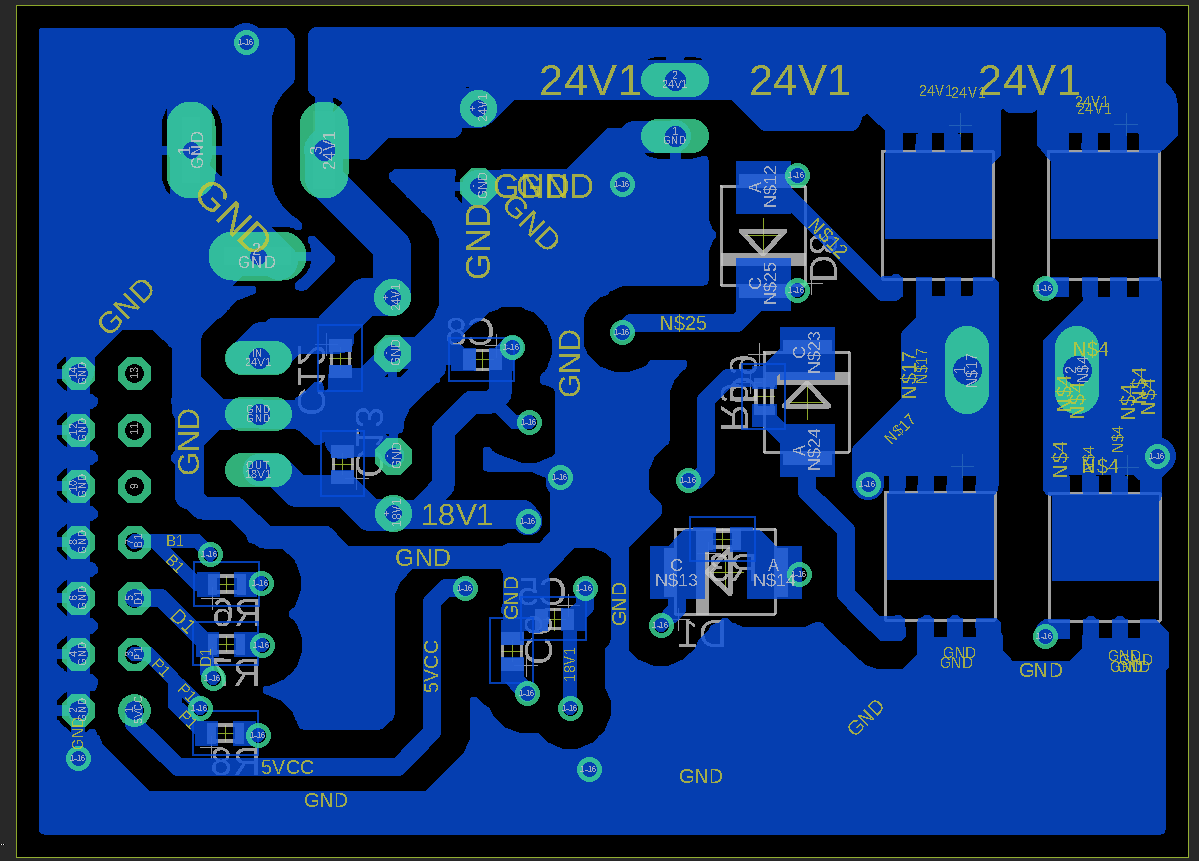
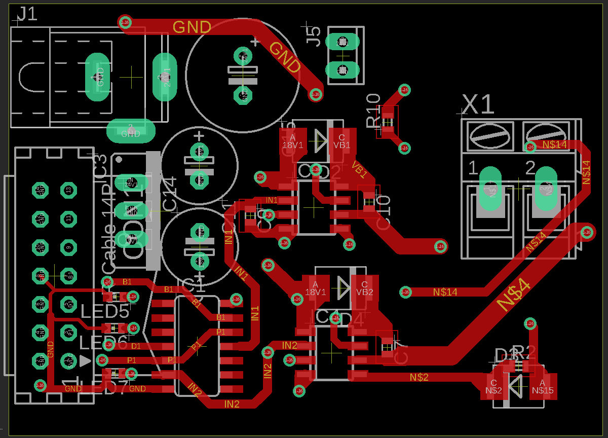
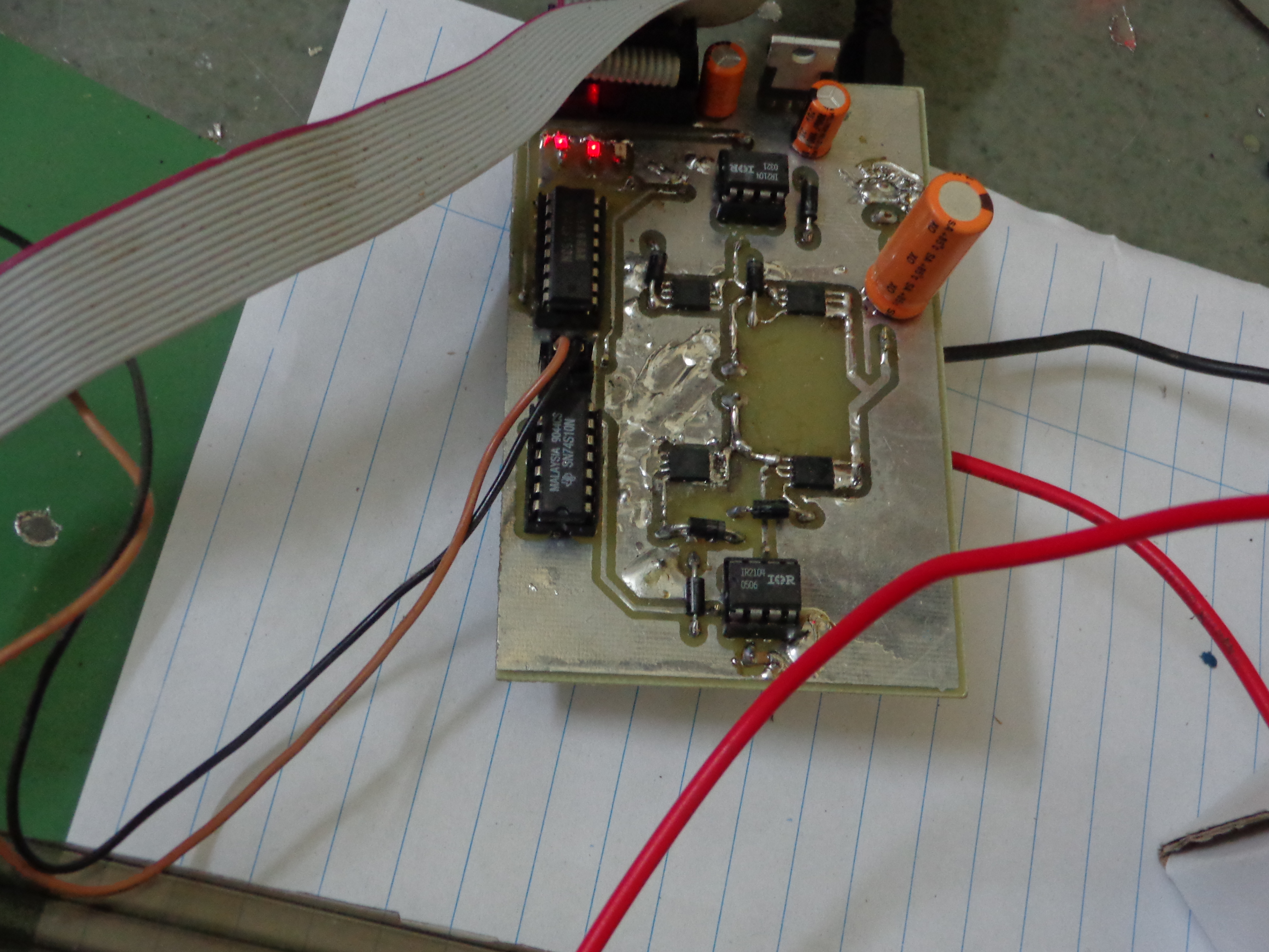
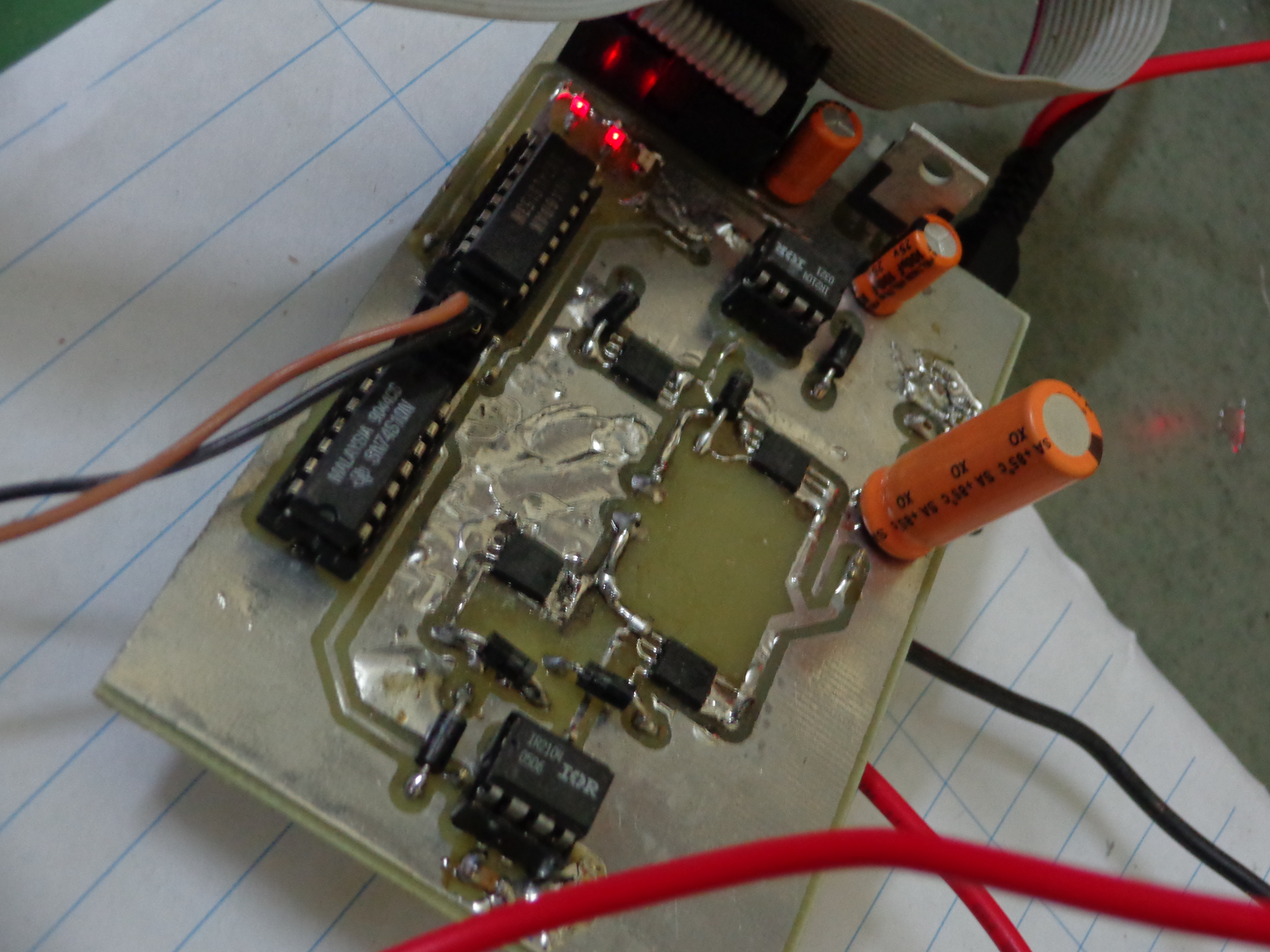
The motivation for this motor driver was to decrease the heat dissipated from the motor driver and thereby increasing the reliability and life-span of the motor driver circuit as a whole. This motor driver was the a version of the IR motor driver that I discussed in earlier post. Instead of using DIP packaged IRFZ48N series MOSFETs, I used Texas Instruments' CSD18501Q5A series SMD MOSFETs. These SMD MOSFETs have really small footprint (smaller than a pinky nail). In Figure 1, you can see the footprint of MOSFETs on the right side that has a h-bridge using four SMD MOSFETs. Also, their RDS-ON is extremely small as compared to the DIP MOSFETs. Therefore, this circuit did not require any physical heat-sinks (like Figure 3). The heat sinking process achieved by providing very thick ground pads that occupied a large area of the PCB footprint.
This motor driver is for bidirectional speed control of only one motor. It requires four MOSFETs for to form a standard H-bridge configuration. The PCB has dimensions of 5.3 cm X 4.0 cm (~ 2.08 inch X 1.57 inch). In perspective of a DC-motor driver capable of providing 5-10 Amperes of continuous current, this board was really a small, tiny, self-containing, and compact board.
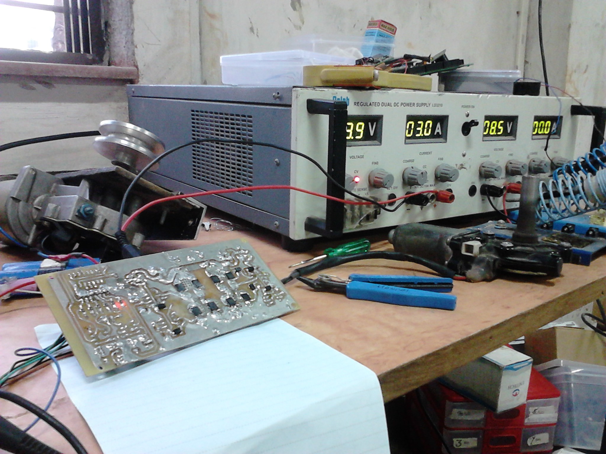
I tested this motor driver on-load with various types of DC motors such as standard, economic, low-end DC motors like these, MAXON DC motors, power-window motor, wiper motor, etc. The later two are high torque motors which require very high power to drive them while former two are high RPM motors that work on low power. In figure 4 you can see the circuit being tested on a wiper motor which drew 3A current at 9V without even putting any load on the motor. With on-load testing the typical continuous current for this particular motor was about 8A.
After working with DIP packaged MOSFETs for several years, I found it astonishing to see those tiny, pea-sized MOSFET carried continuous currents over 5A for several minutes on-load at operating voltage of 24V. Even more surprising was that the MOSFETs did not heat crazily unlike the DIP MOSFETs at the same power levels. I still cannot fathom the fact that a tiny thing made from silicon and other fancy stuff can conduct excess of 5A currents continuously without burning out!
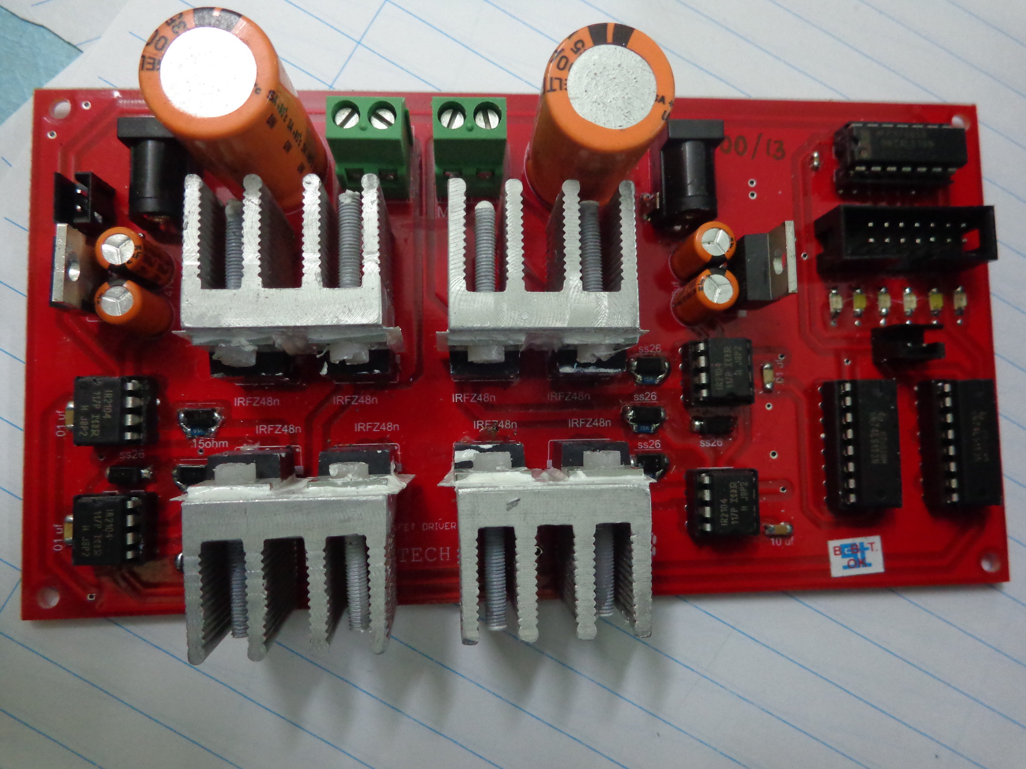
Here is the motor driver PCB in action on-load with a wiper motor that requires high power to drive because it is a high-torque motor. This specific motor circuit was a dual version of the PCB that we are discussing in this post and it could driver 2 motors independently and simultaneously. As you may have figured out that it was an obvious quick-and-dirty prototype PCB. But being the first version, it worked pretty well on its maiden on-load testing!
I remember that I was extremely happy to see the prototype working like a charm because soldering those 8 SMD MOSFETs took eons. With a little exaggeration, I had to put my blood, sweat, and tears ensuring that the tiny tiny pins of the MSOFETs did not get short! I think those pins are like 0.5 mm apart at the best (Figure 1). You short Gate to Drain and boooom ..... expect 4 hours of soldering (and life) to go in vain!
Circuit Components:
- IR2520DS IC SMD (IR2104 IC DIP): Half bridge MOSFET driver IC that works on the concept of bootstrapping.
- CSD18501Q5A MOSFETs: SMD MOSFETs from Texas Instruments.
- 7818 Voltage Regulator: Generates 18 V required by the motor driver ICs.
- 1N5819 Diodes: Freewheeling diodes.
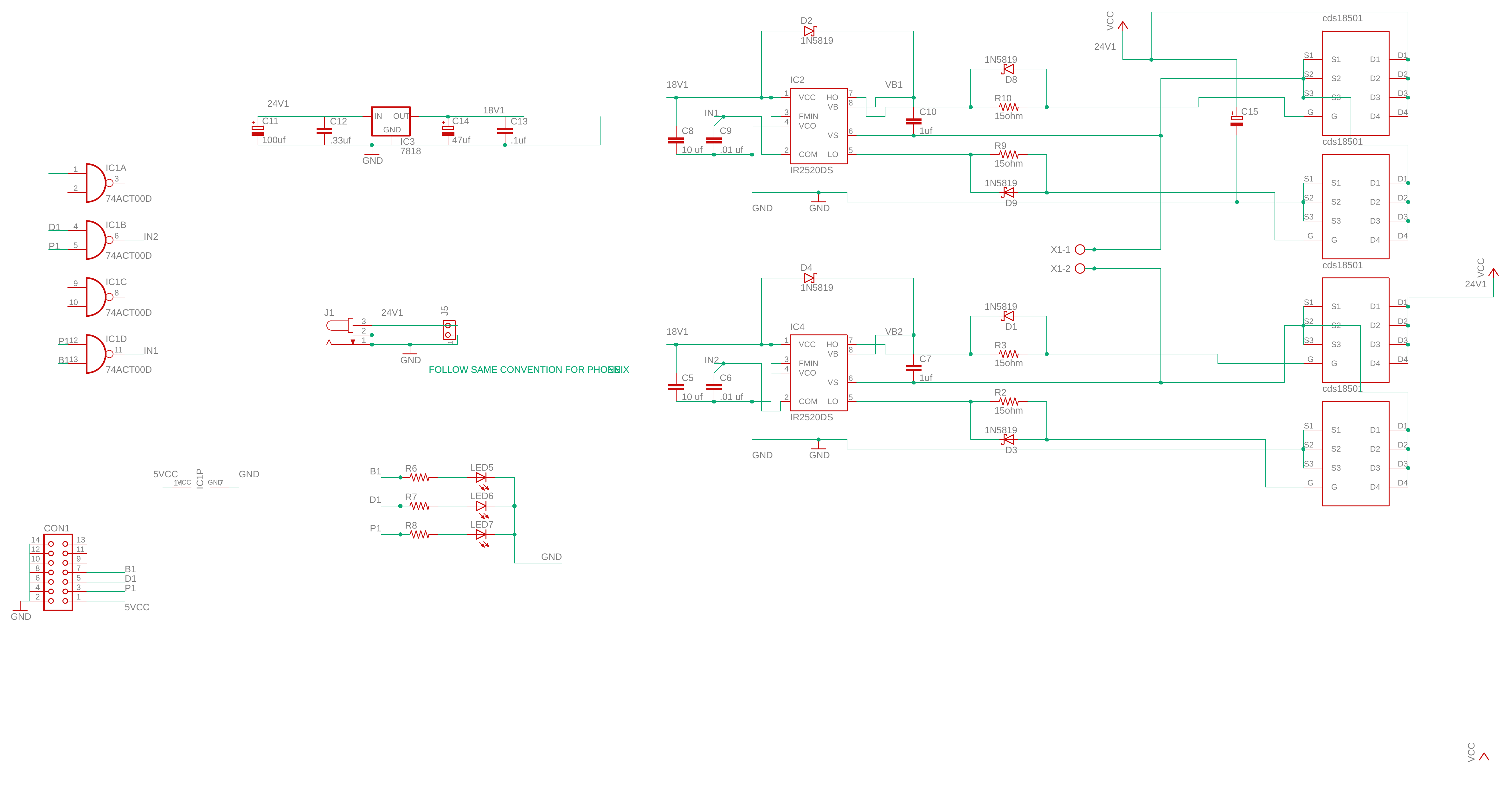
- MUX and Gates: The exact part numbers can be found in the schematic image below.
- LED, diodes, and RCL components: Signal indicator LEDs for PWM, Direction, and Brake signals. Voltage regulator protection diode. The exact values of resistors and capacitors can be found in the schematic image below.
- Connectors: Header connectors, IC holders, Power Jack connector.
Circuit Schematic: