
High Power DC Motor Driver using Relays and MOSFETs
Introduction:
A motor driver consists of an H-bridge with a mechanism to control the speed of the motor. A basic H-bridge circuit is consist of four switches and a motor. For speed control one can use four MOSFETs as the switching devices to control the on and off time of the motor. Speed control is achieved by applying Pulse Width Modulated (PWM) signal to the Gate of the MOSFET.
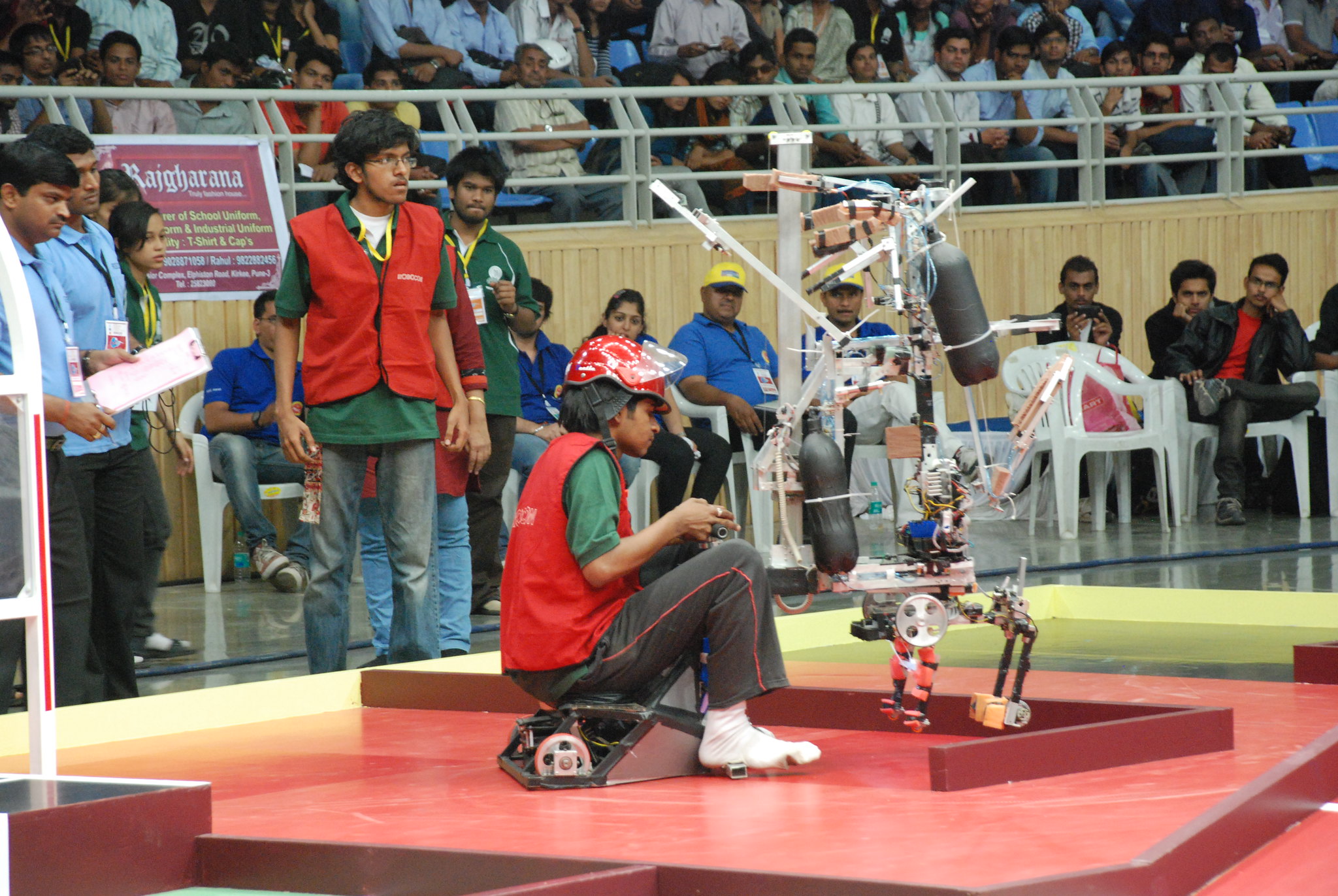
Relay-MOSFET driver in this project is a simple circuit in which the H-bridge was constructed using two electromagnetic relays (EMR) used as 4 switches. They were used to control the spinning direction of the motor. Now to control the speed, an N-channel MOSFET IRF460N was used for switching of the motor. PWM signal given to the GATE of this MOSFET controlled the on and off time of the MOSFET which in turn decides the amount of time for which current flows through the motor. A PWM of 50% duty time keeps the motor on for 50% of the times and thus making it spin at 50% of the speed it would achieve with a 100% duty cycle PWM signal. In this way by changing the duty cycle of the PWM signal, we can control the ON and OFF times of the motor. This MOSFET was required to carry large amounts of current hence a power MOSFET IRF460N was used. This motor driver was used in the Manual Robot that my robotics team designed for the robotics competition - Robocon 2012. The manual robot was required to be driven by a manual operator sitting on top of the robot. It was an enormous challenge to design a motor driver circuit that will withstand the high currents and high power required to carry our 65 Kg manual operator. Here is a picture of my team's manual robot in action.
Typical average on-load current for this driver was about 5-10 Amperes, and peak current would go up to 15-20 Amperes. For a circuit running at 24 V, these are really high current ratings. To put this in perspective, a typical average scale motor driver carries about 2 Amperes of continuous current on-load. On average the relay-MOSFET motor driver consumed 240 W power on-load.
Circuit Components:
- Relays: Two 10A /24VDC relays were used as 4 switches for direction control.
- ULN2003A IC: It is a Darlington pair IC. The current required to drive the coils of the relays was fulfilled by this Darlington pair IC.
- MOSFET (IRF460N): This power MOSFET is capable of handling a large quantity of continuous currents and also its RDS(ON) is few milliohms, hence selected. Heat sink was also provided for proper heat dissipation.
- Diodes: These are 2 freewheeling diodes used whenever freewheeling was required by the motor.
Printed Circuit Board:
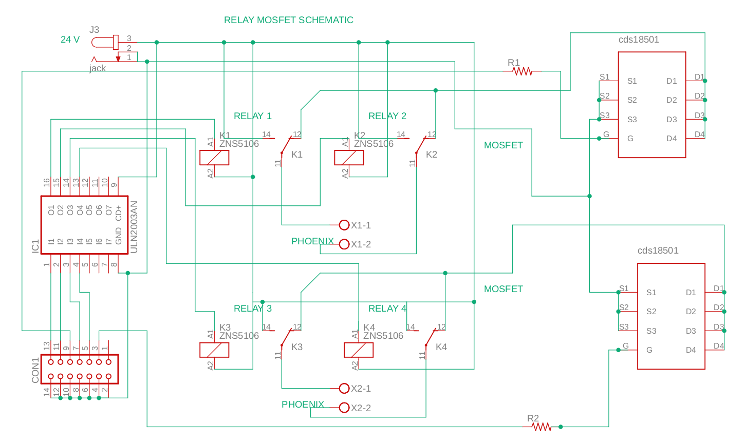
Complete design of this motor driver can be found in th repository links above. Here is the schematic of the PCB.
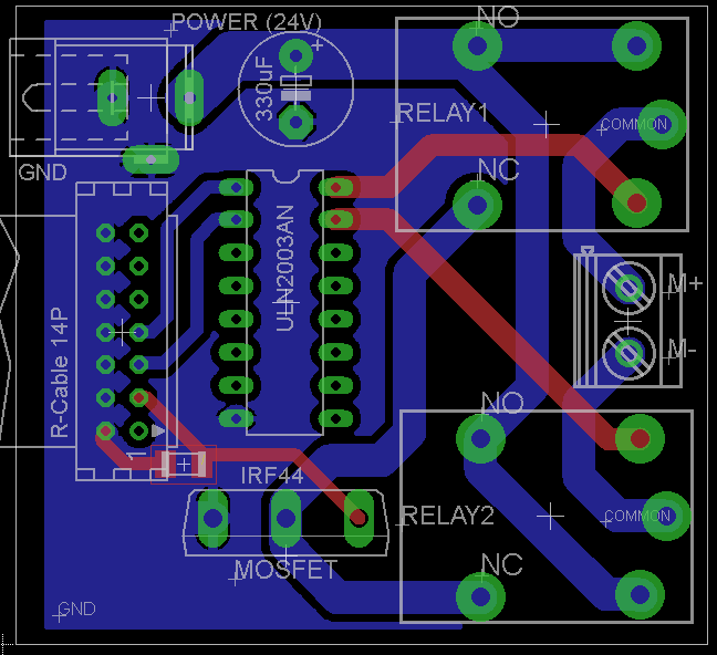
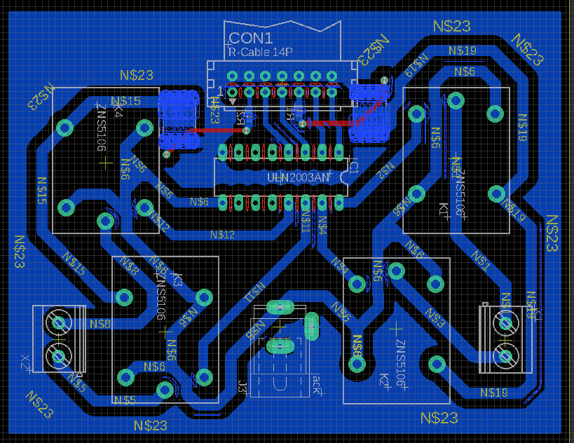
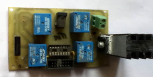
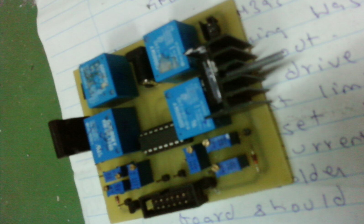
Here are some screenshots of the board files from EAGLE PCB design software and corresponding circuit board.
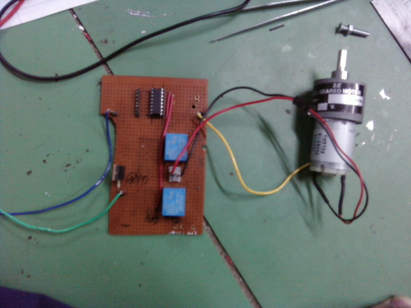
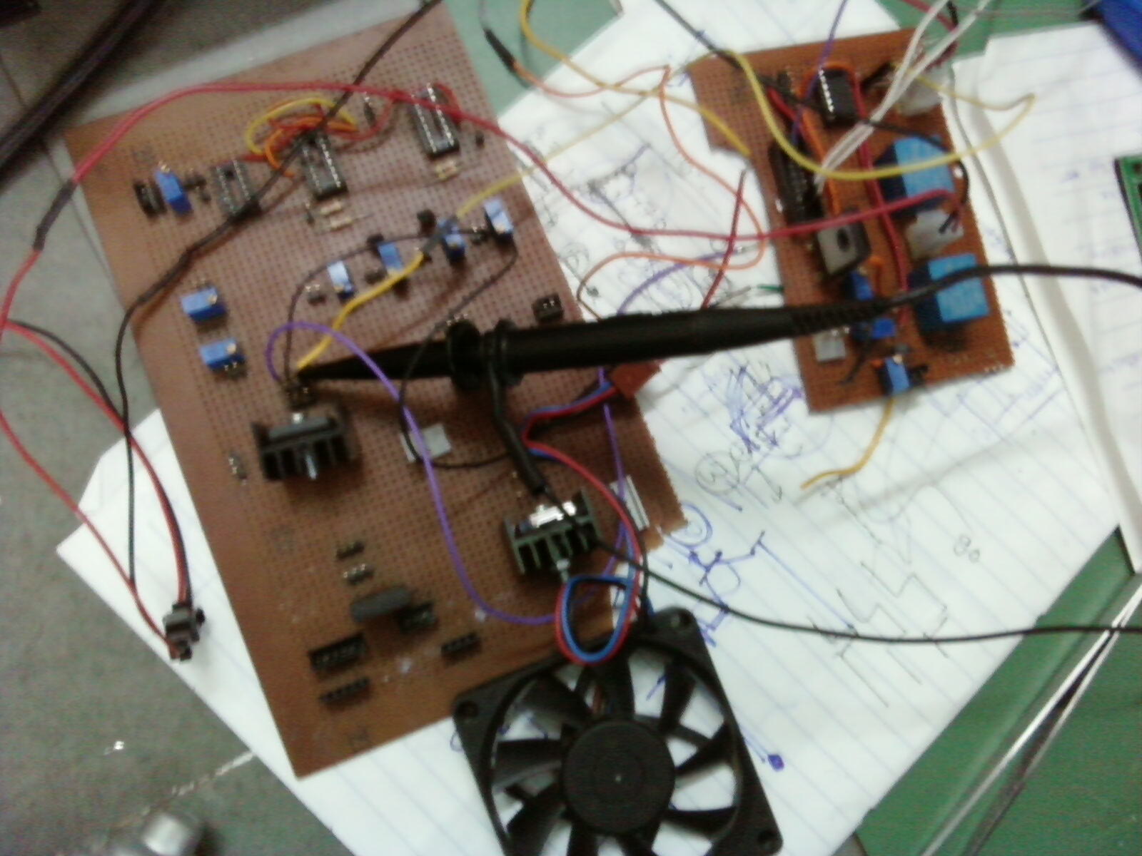
Here are some of the initial prototypes that I tried:
Practical Performance:
Frequency Response:
At lower frequencies of PWM (less than 8 KHz), MAXON R30 motor would respond to the PWM only after 10% duty cycle. At higher frequencies like 16 KHz or 32 KHz it would respond only after 30% duty cycle. This is because the response of the MOSFET at lower duty cycle was not good which further worsens at higher frequencies.
Linearity:
The response of motor to the PWM was not linear. If 50% PWM is applied then the ideal voltage across the motor should be 12 Volts, but practically it departed from this value. To achieve linearity, we experimented with a transistor to control the GATE voltage.
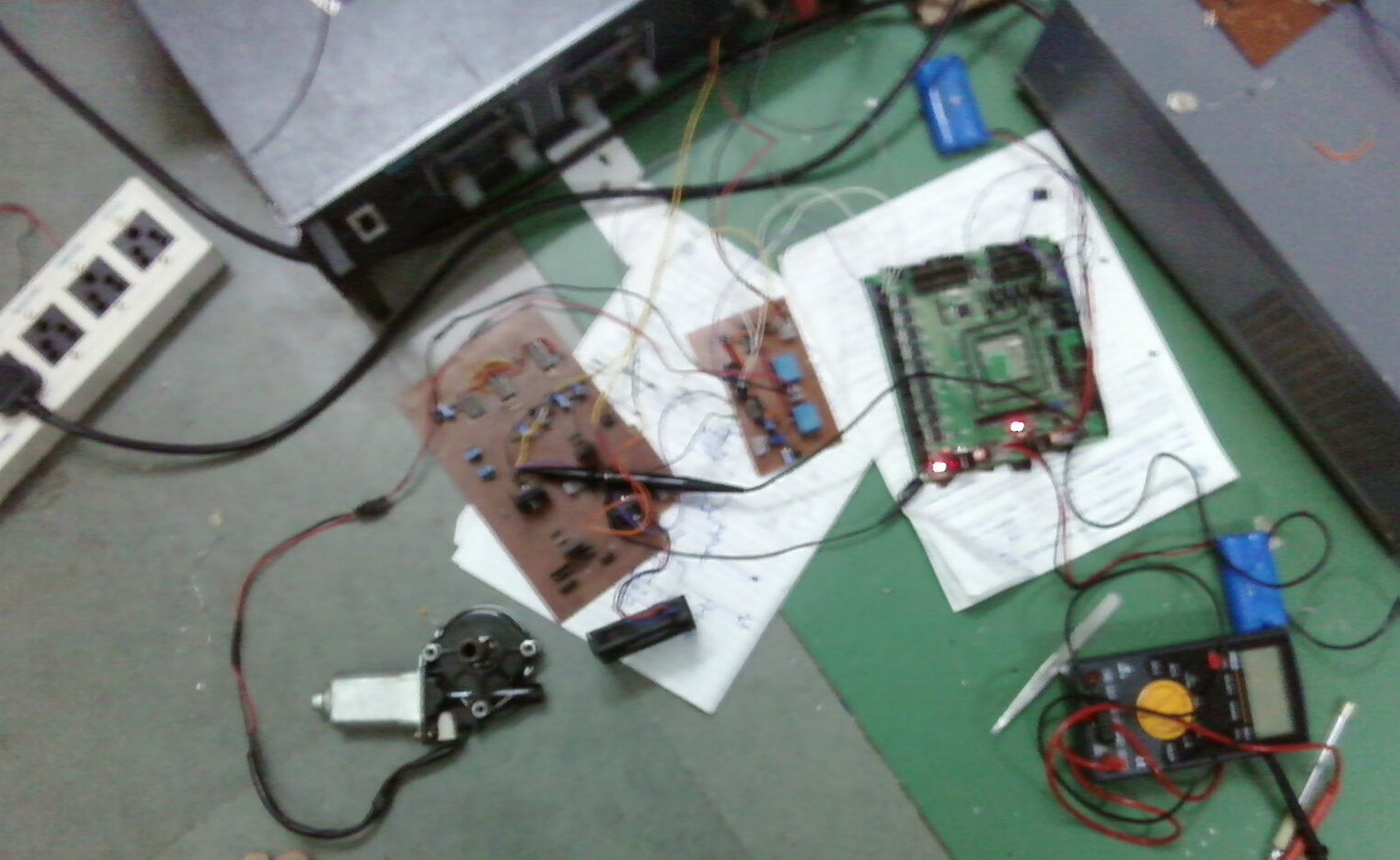
Load Testing:
This driver was tested several times by drawing a current of about 5 A to 6 A continuously for two hours. During this, the MOSFET would show normal degree of heating with a decent heat sink. We mounted this motor driver on the manual machine and rode it a few times with a total load weight of 75 Kg (machine + manual operator). We observed that ULN2003 would frequently get damaged at its ground pin. The same was noted when used for raising and lowering of the grabbing jaws of the manual machine. We concluded that a probable reason was the voltage fluctuations present in the GROUND plane of the circuit during on-load operations. These fluctuations produced by the motor were going directly to the GND pin of ULN IC and this would ultimately damage the IC.
Other:
I also tried another version with DRAIN connected to VCC. With this configuration the SOURCE was connected to the motor and it went floating causing the circuit not to work. Freewheeling diodes D1 and D2 can be connected whenever freewheeling is required and can be removed otherwise.
Possible Improvements:
- To avoid the damage to ULN, an inductor can be placed between power ground and ULN’s GND for isolation.
- Better MOSFETs with higher power can be used.