Printed Circuit Boards
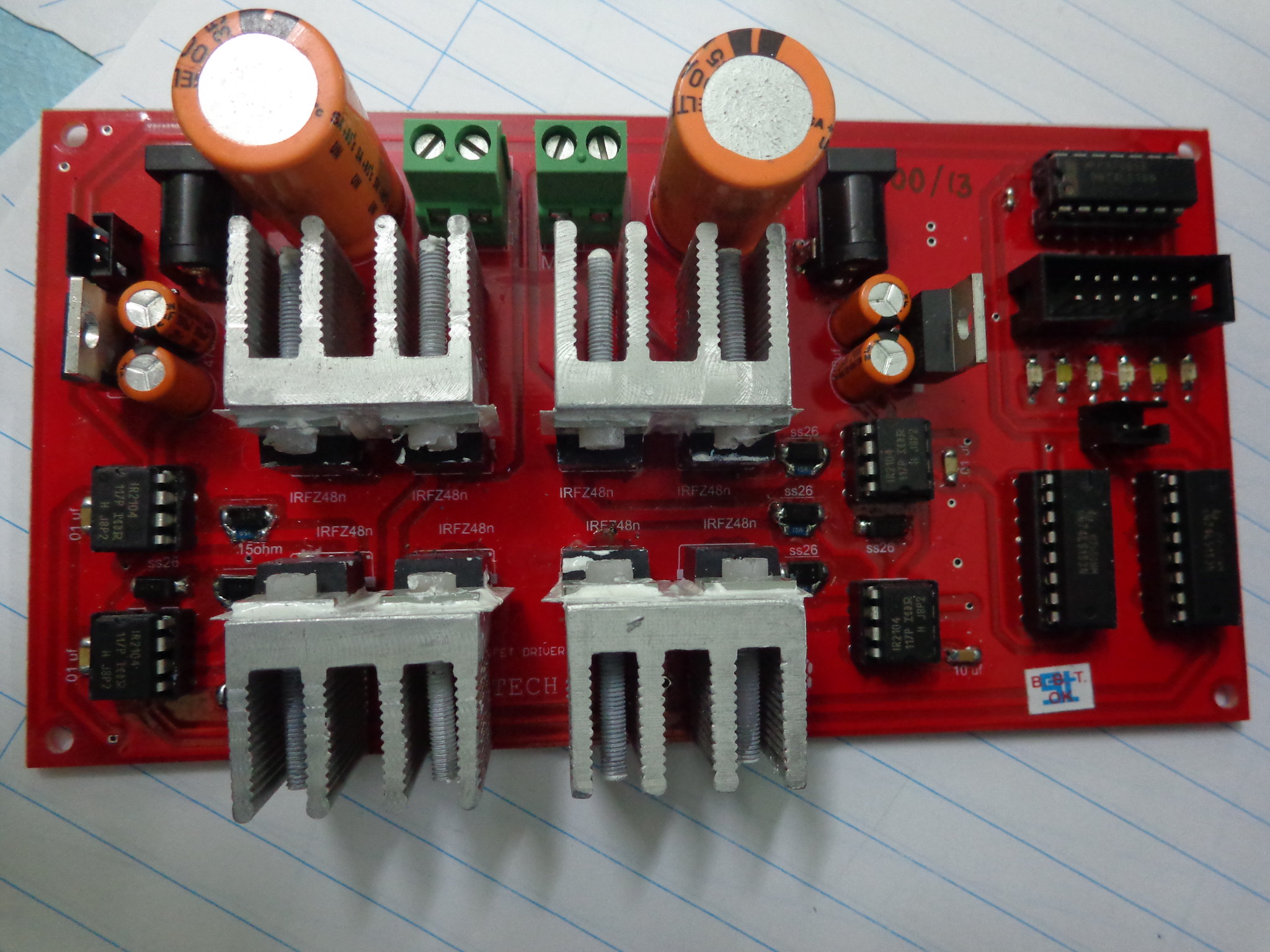
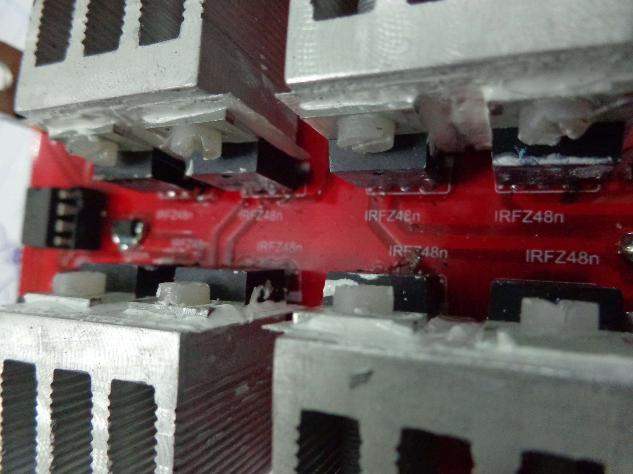
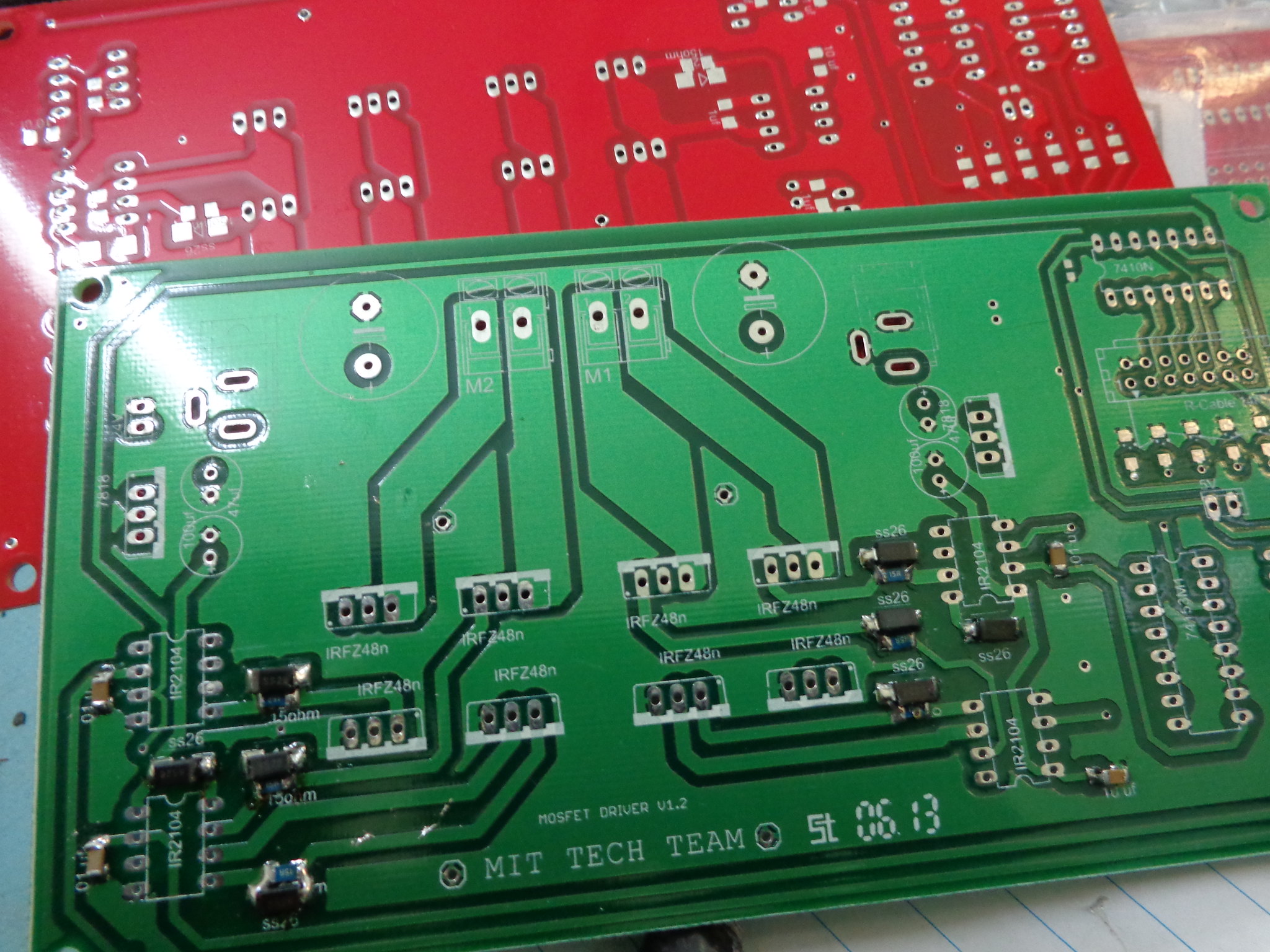
I designed the layout of this high-power MOSFET Motor Driver that drives 2 motors independently. The original configuration of this circuit was developed by my teammates Bhairav Shah and Harshal Kalyane in 2011. The main goal was to build a highly robust and highly reliable DC motor driver that yielded currents over 15 Amperes continuously at 24V DC voltage. During Robocon 2012, this driver drove a 23 Kg (50 lbs), semi-automatic Robot that carried a person weighing 70 Kg (155 lbs). The circuit was build with a MOSFET driver IC that worked on the concept of bootstrapping. I spend several weeks on improving and revising the board that ended up with several version of the board. I had to obey some of the strict high-power PCB circuit design rules to avoid issues such as crosstalk, impedance mismatch, and electromagnetic interference/noise due to motor and its high currents. This design turned out to be very reliable and never failed during its deployment in actual one-on-one matches against other teams/robots. Even after 5 years when this motor driver was first introduced, I feel extremely passionate and nostalgic about it. This project will always be in the top-5 favourite projects of mine.


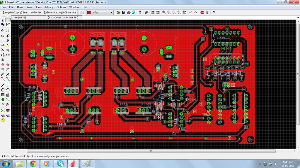
Routing in progress using EAGLE PCB design software:

Brand new PCBs:
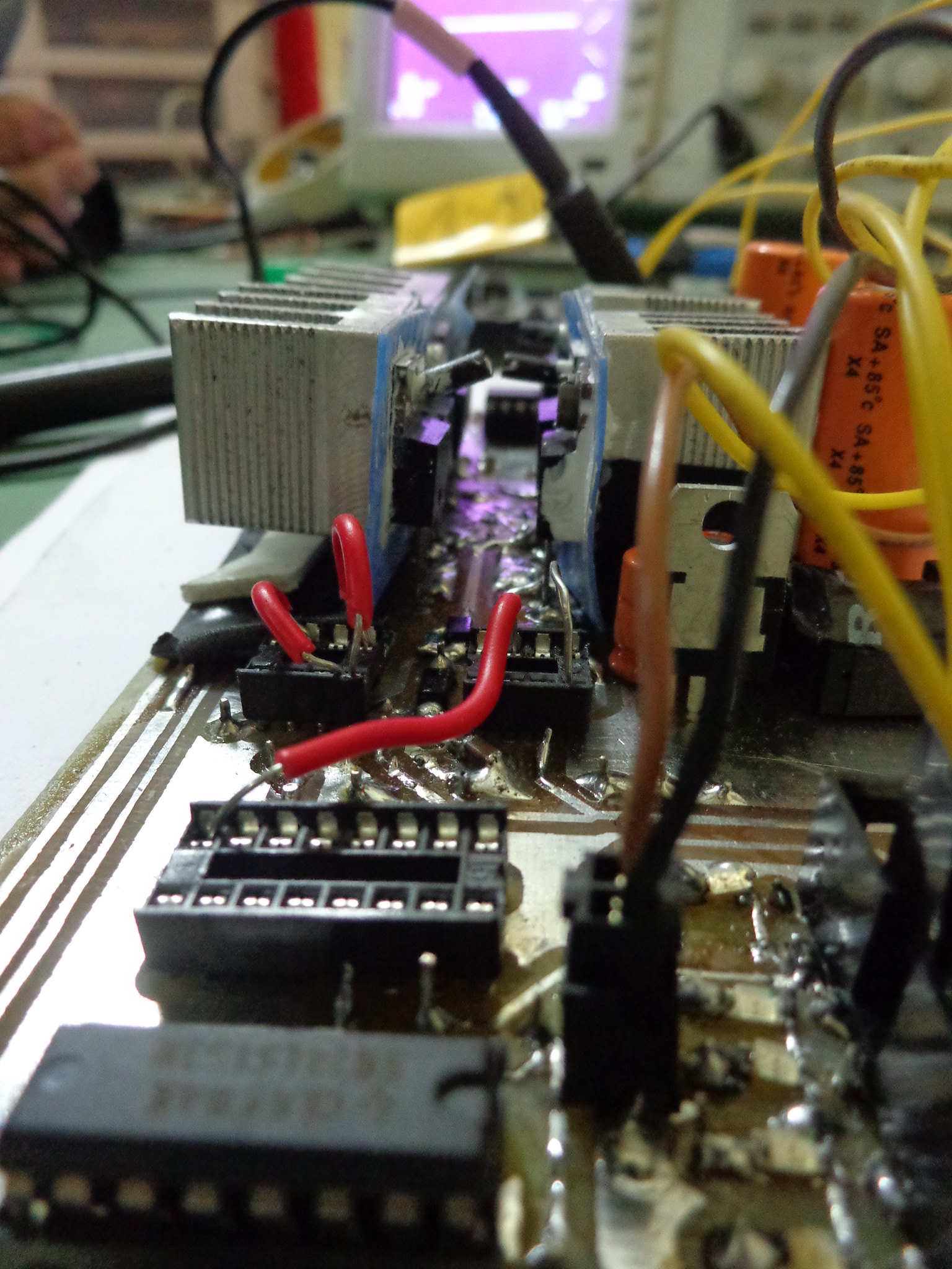
Signal-testing a quick-and-dirty prototype:
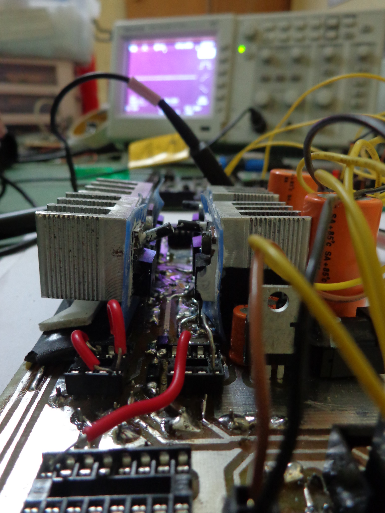
A major malfunction that exploded the MOSFETs in the prototype, which literally caused the bot to catch fire. Took some efforts to extinguish the fire! Fire was so huge that I panicked and asked my buddies to get a bucket of water in that moment. Not to mention that a 24V LiPo battery was still connected. My buddies still make fun of me for that. LOL.
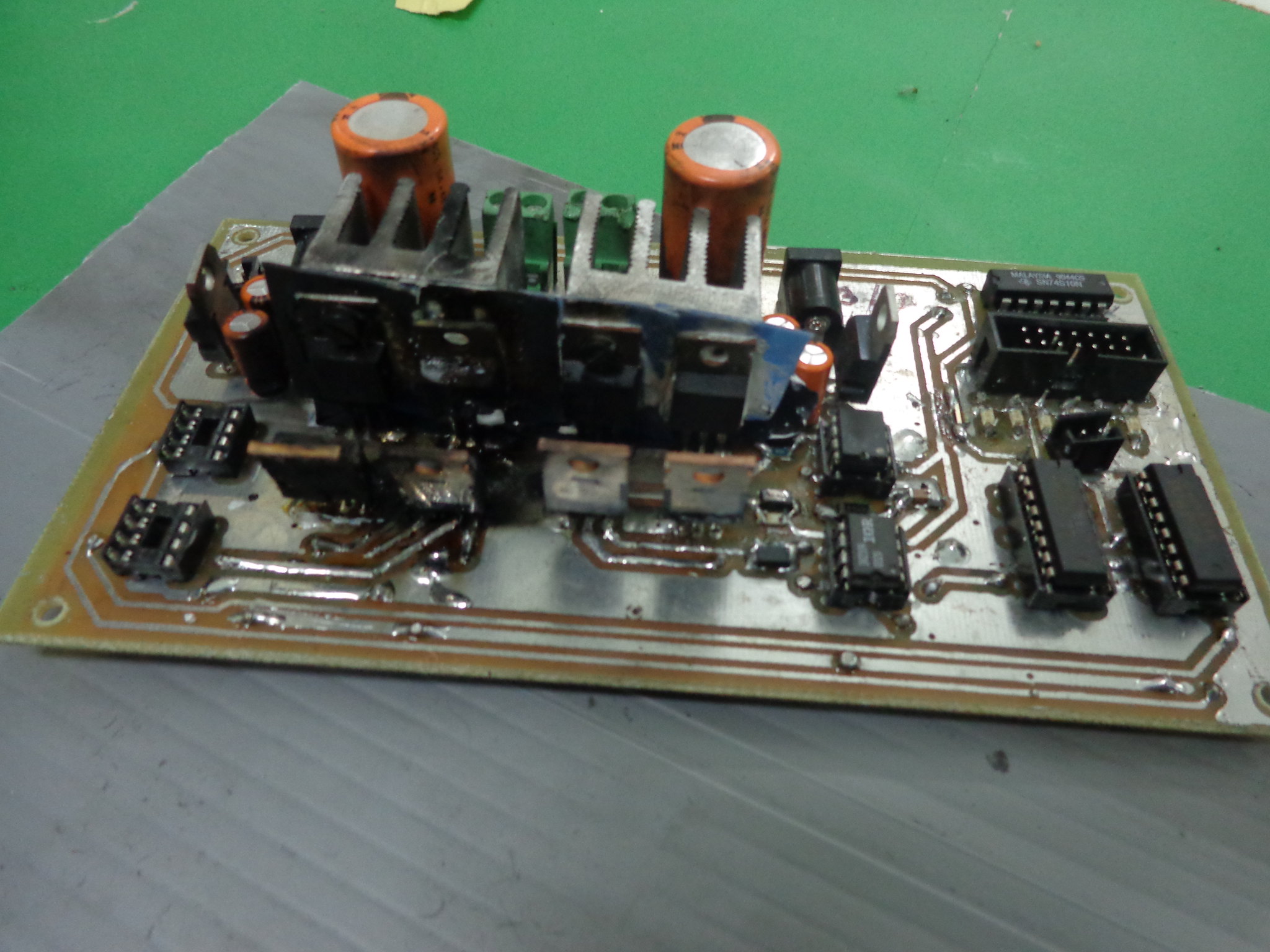
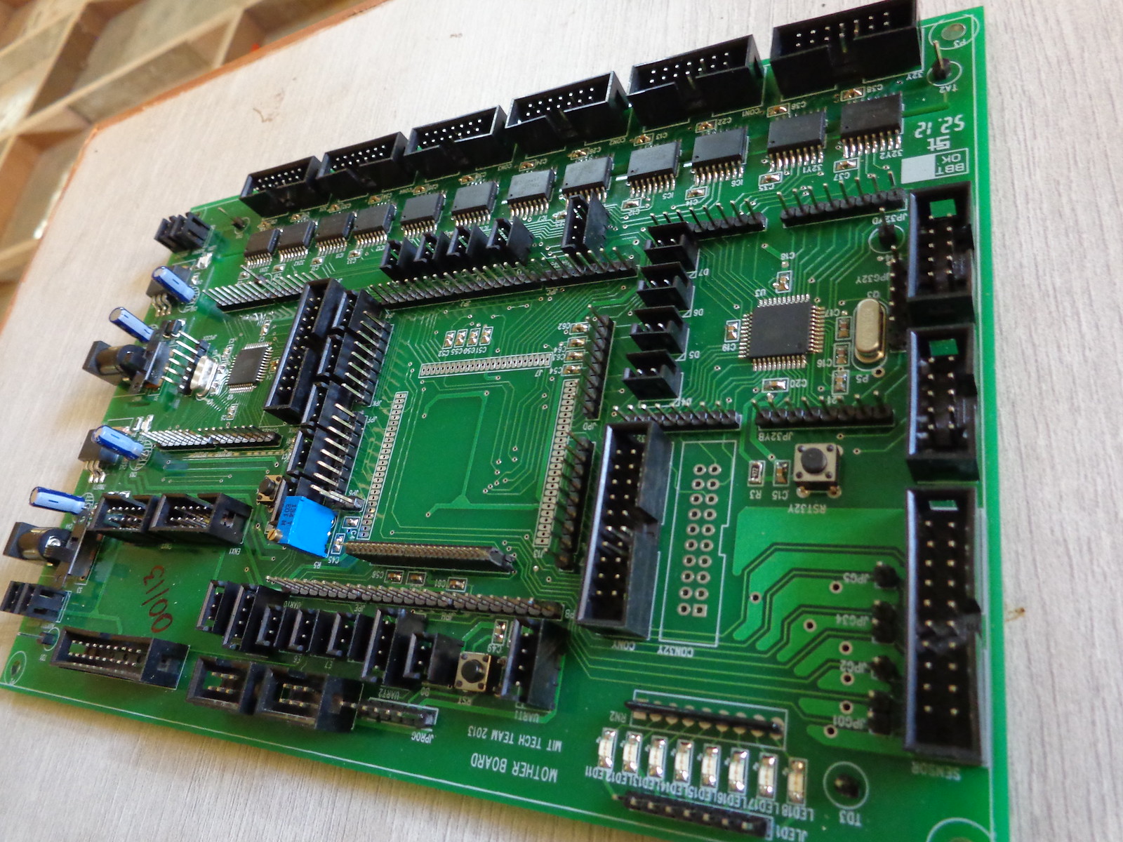
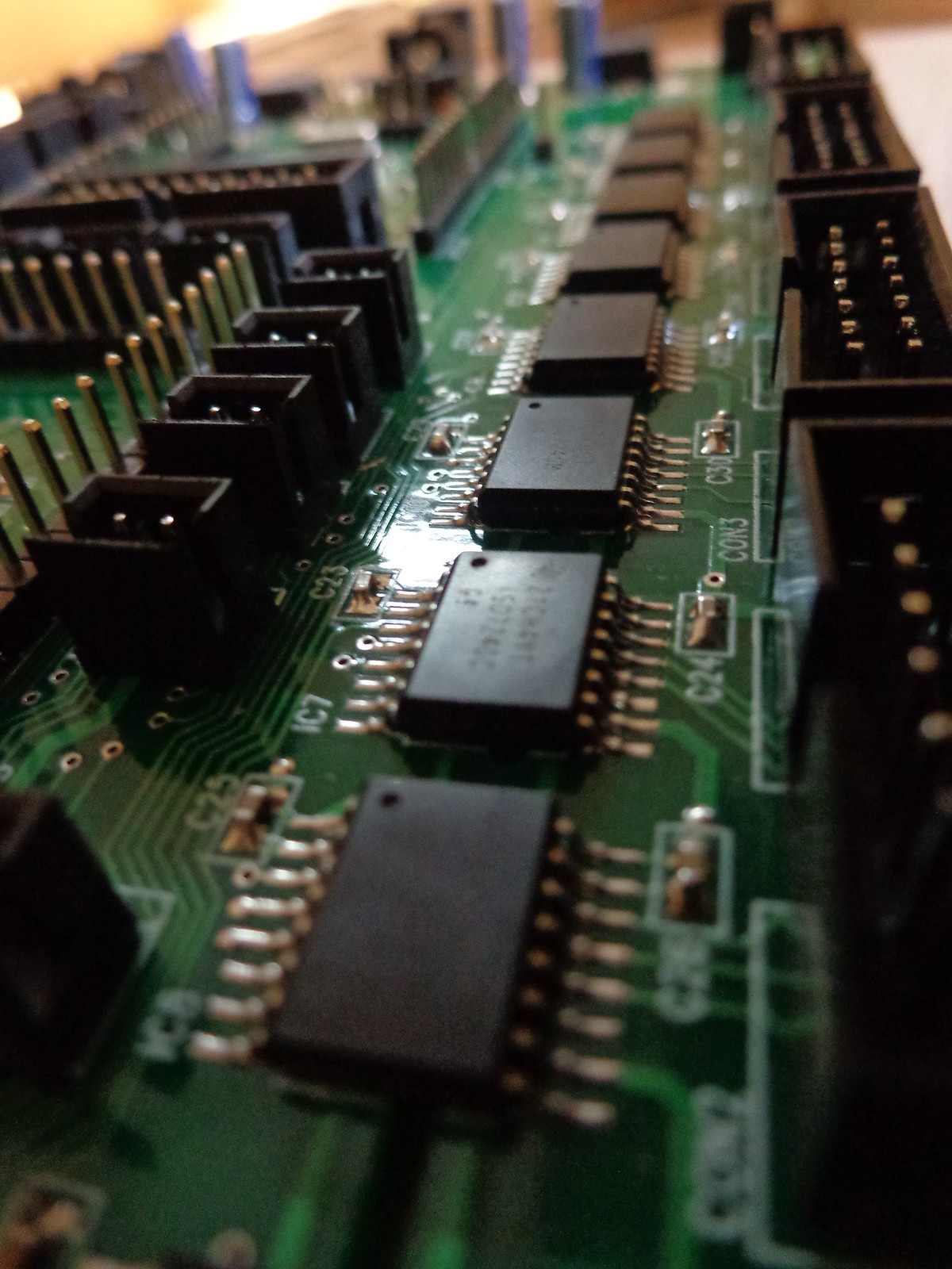
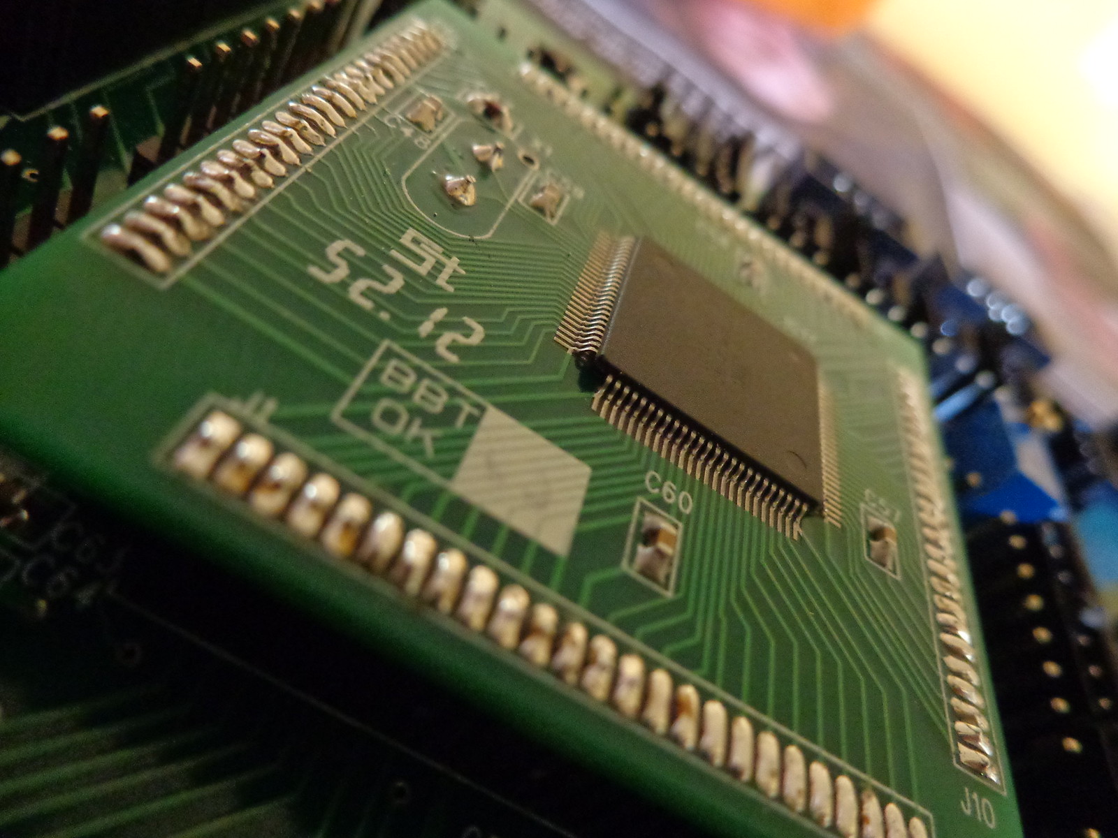
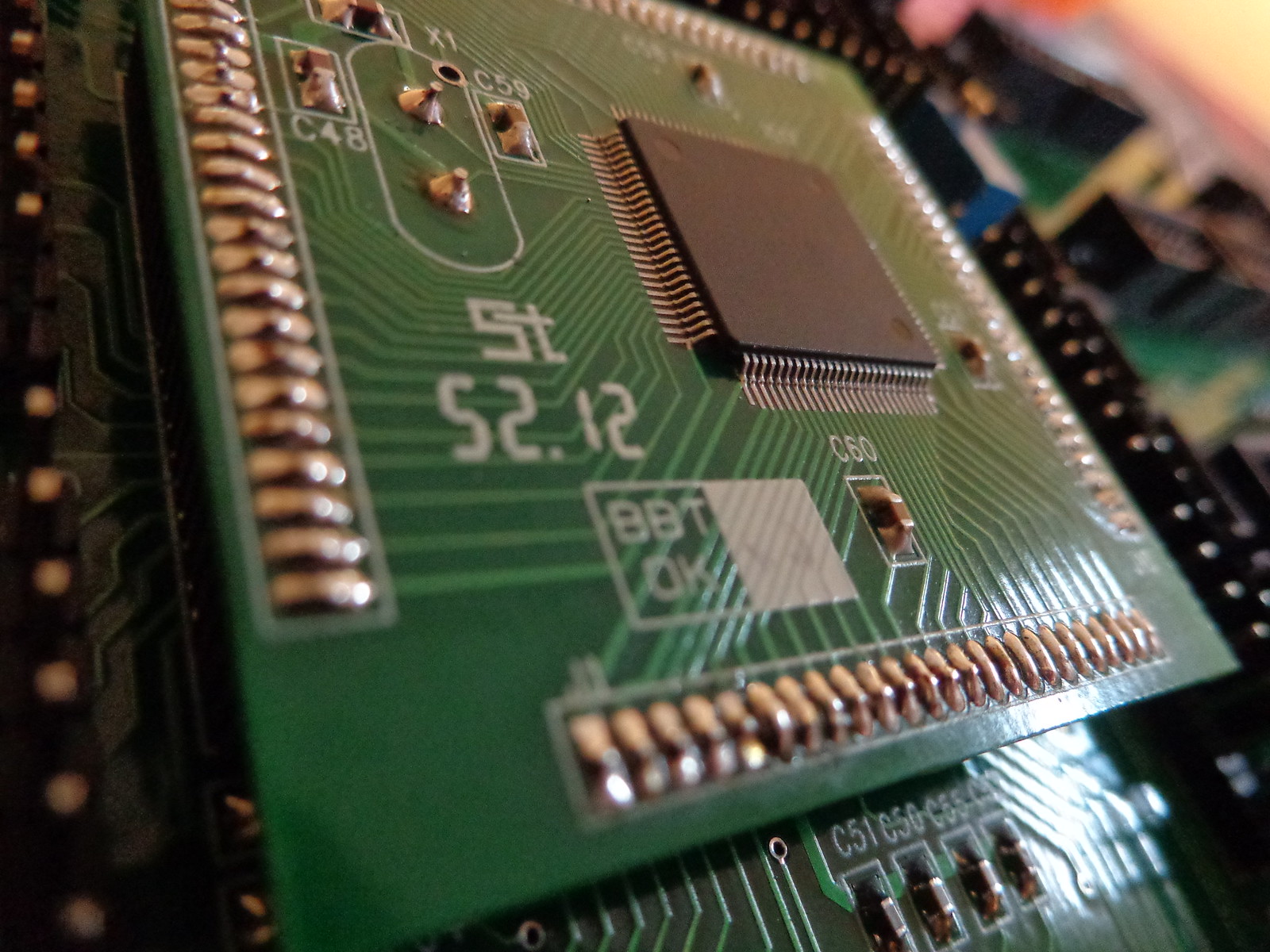
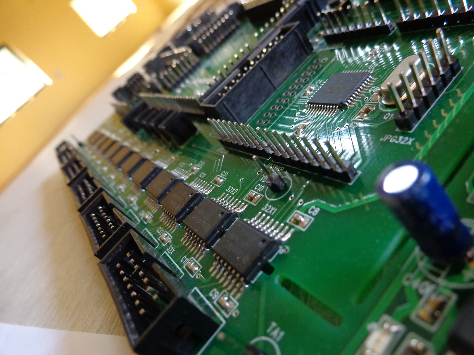
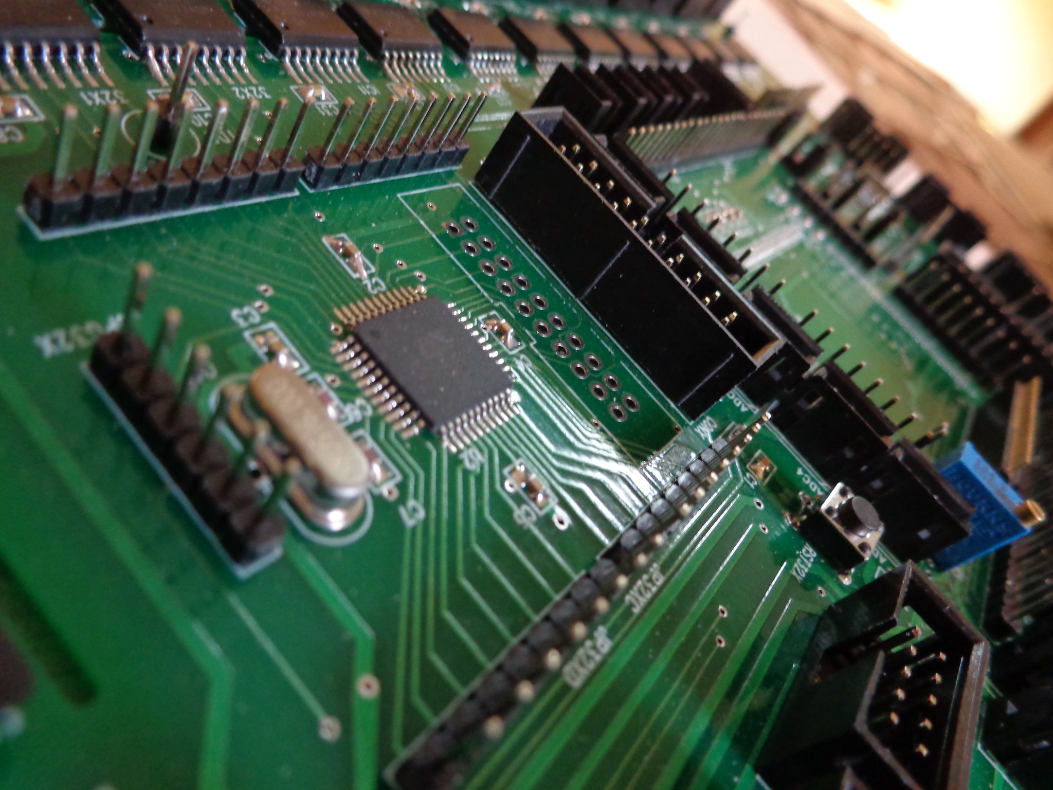
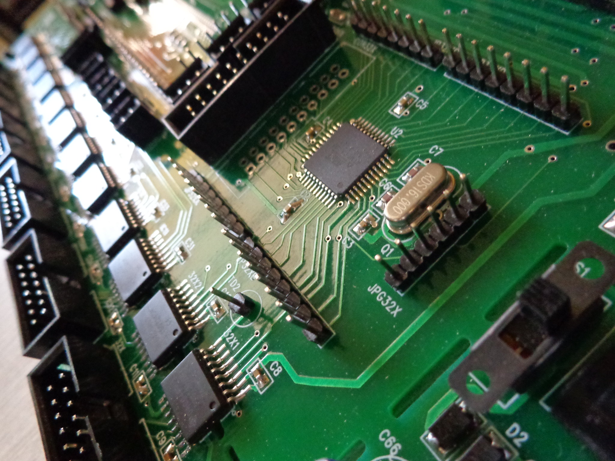
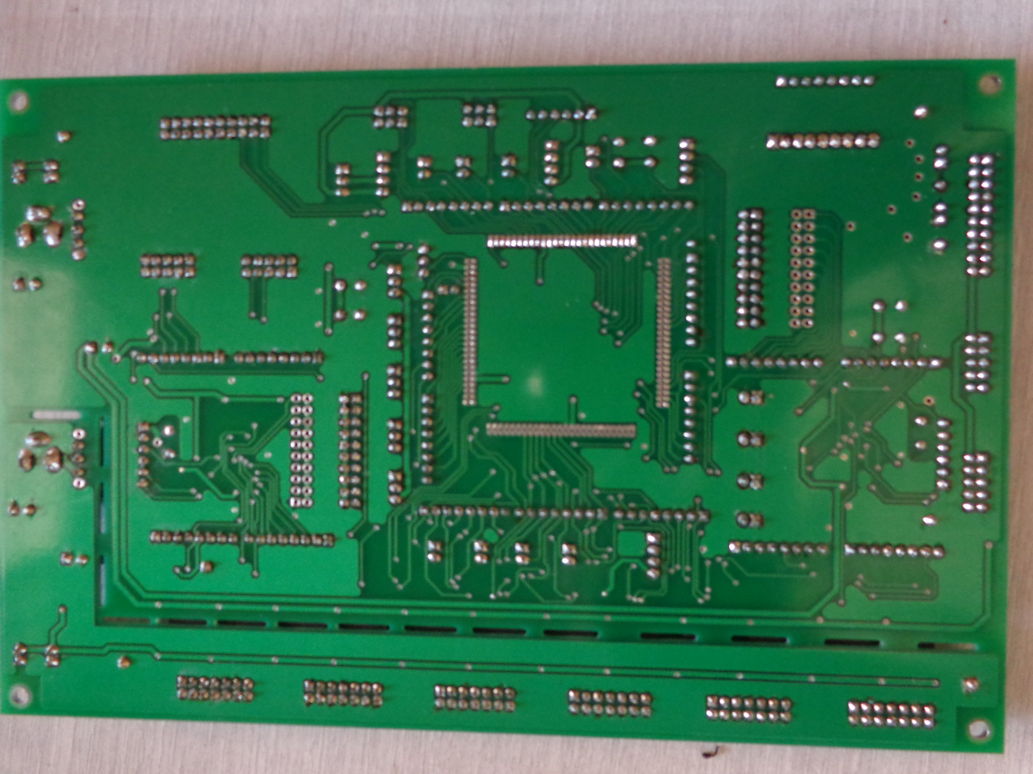
Motherboards that my Robotics team used to drive different robots. The design and layout was finalized by electronics team that I was a part of. Every year we go through several iterations of this board to finalize the best and optimum design.
