ATMEGA32 Micro-controller Board to Interface Sony PS2 Controller
Introduction and Motivation:
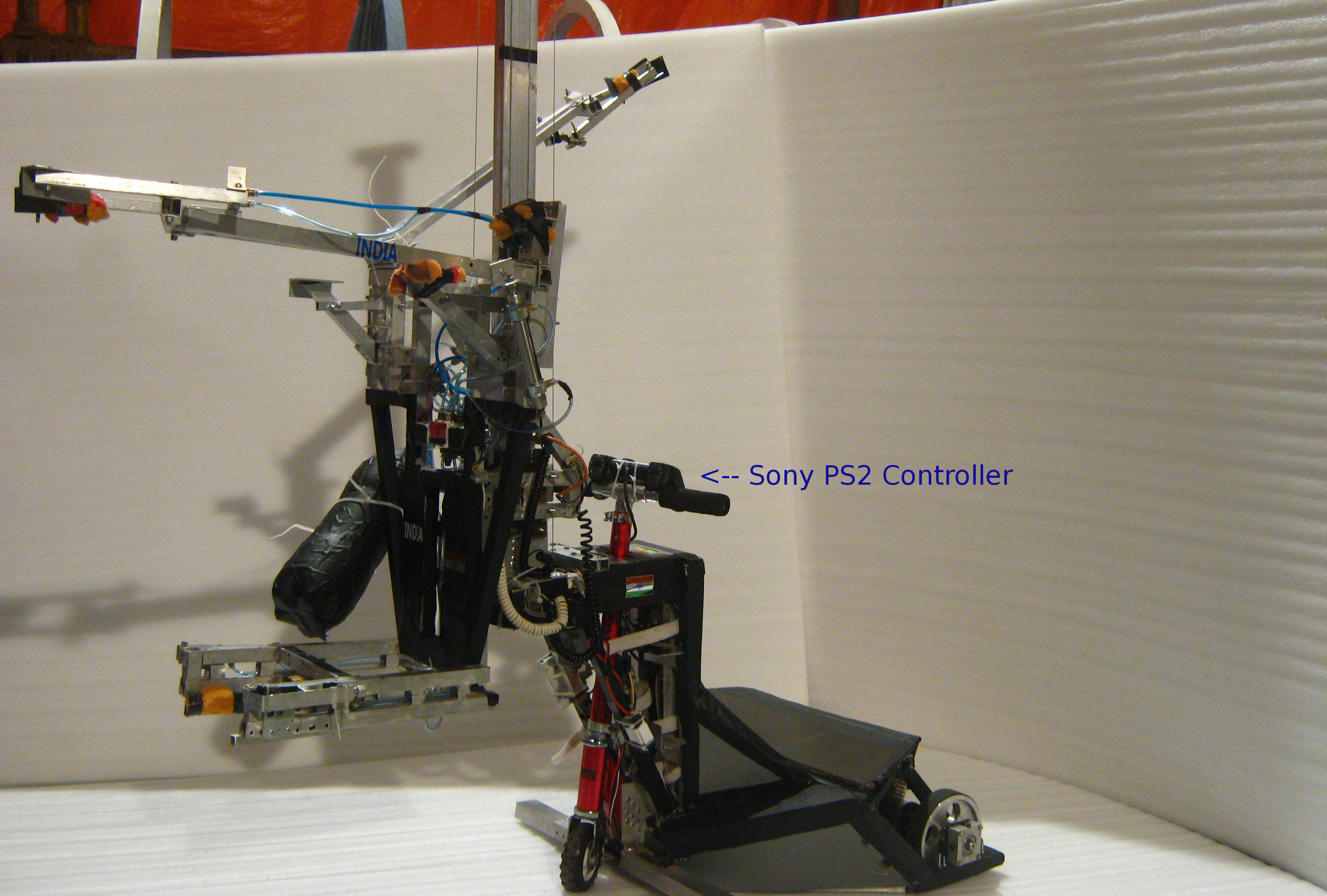
The semi-automatic robots that my robotics group designed were usually maneuvered using a Sony PS2 controller. As a primary function, PS2 controlled the speed and direction of the robots using the analog joysticks on the controller. The secondary functions were turning jaws open and close to grab objects, controlling secondary motors on the robot such as the one used to raise or lower the gantry system in the front. The image (Figure 1) below shows one such semiautomatic robot that an operator controlled using the PS2 controller.
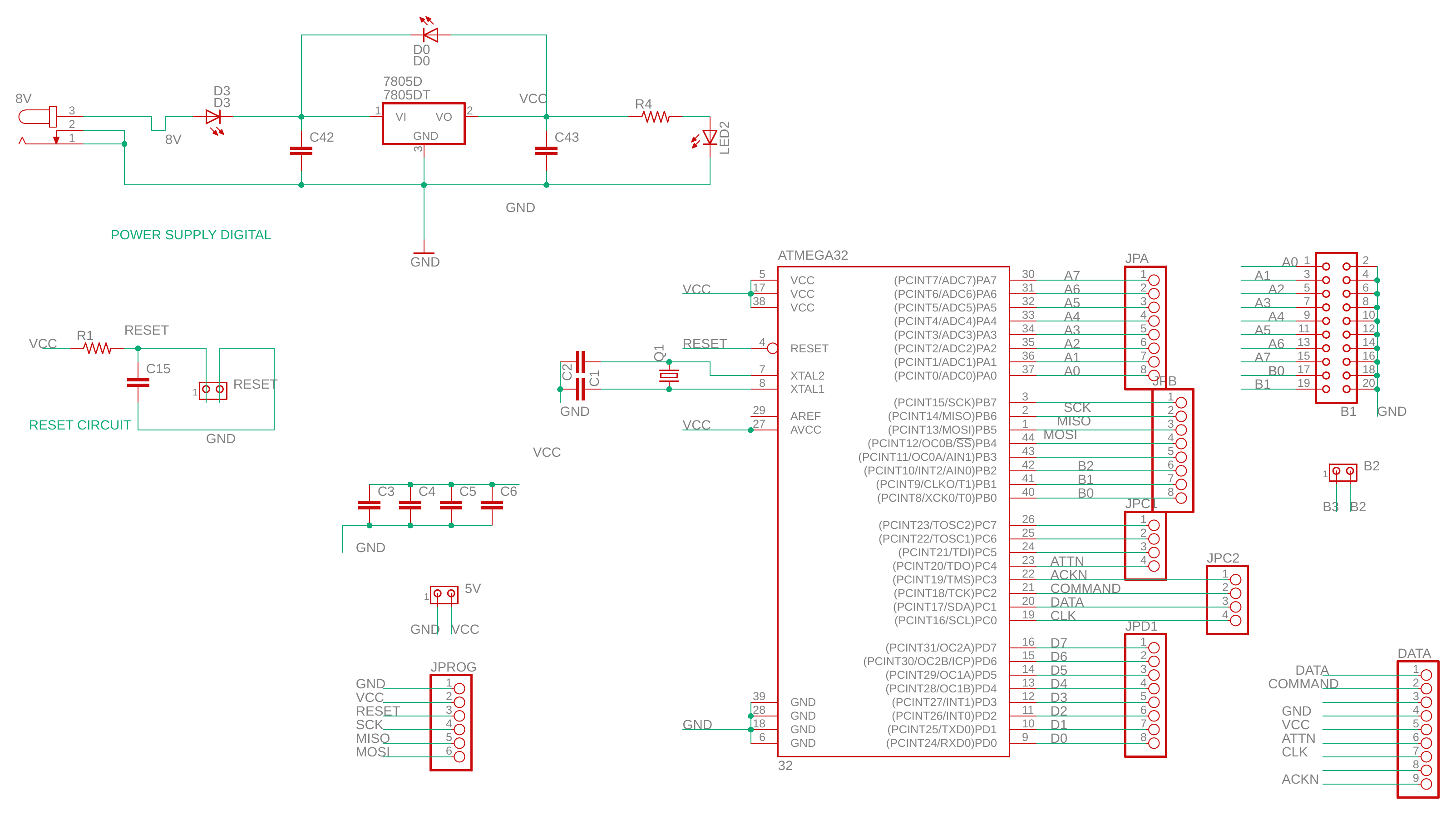
To achieve PS2-based control, a master micro-controller onn the robot reads the signals coming from PS2 via PS2 specific connector. For this connector, the signals are - DATA, COMMAND, GND, VCC, ATTN, CLK, and ACKN. In initial versions of PS2 controller PCB, we fed the signals coming from the PS2 directly to our master micro-controller (Atmega2560) that also handles algorithms of forward-inverse kinematics, path planning, sensing, etc. Control signals coming from PS2 were fed directly to the master micro-controller. Master converted these signals in appropriate motor speeds and directions. However, as we moved from simple two-wheel driver to a holonomic driver system for the robots, the master started handling velocity control algorithms of four motors simultaneously. This caused master micro-controller to get overloaded as it handled many computationally expensive algorithms simultaneously. That is why we decided to isolate the PS2 signal processing from the main algorithms running on the master micro-controller.
One solution to avoid processing of PS2 controller signals on the master micro-controller was to create a modular design. We decided to design a PCB with a micro-controller that solely handled and processed the PS2 signals before routing them to the master micro-controller. Hence, modularization was the primary motive behind the design of this PCB that isolated PS2 signal processing from main algorithms of navigation and sensing on our semi-automatic robots. We deployed this modularized approach the next year on our semi-automatic robot. While my other teammates worked on the software part of modularization and isolation of the algorithms, I worked on the PCB design. After multiple prototypes, I decided on this specific prototype which was compact for our robot that year (as shown in figure 2 - the robot on top with a PS2).
This motor driver is for bidirectional speed control of only one motor. It requires four MOSFETs for to form a standard H-bridge configuration. The PCB has dimensions of 5.3 cm X 4.0 cm (~ 2.08 inch X 1.57 inch). In perspective of a DC-motor driver capable of providing 5-10 Amperes of continuous current, this board was really a small, tiny, self-containing, and compact board.


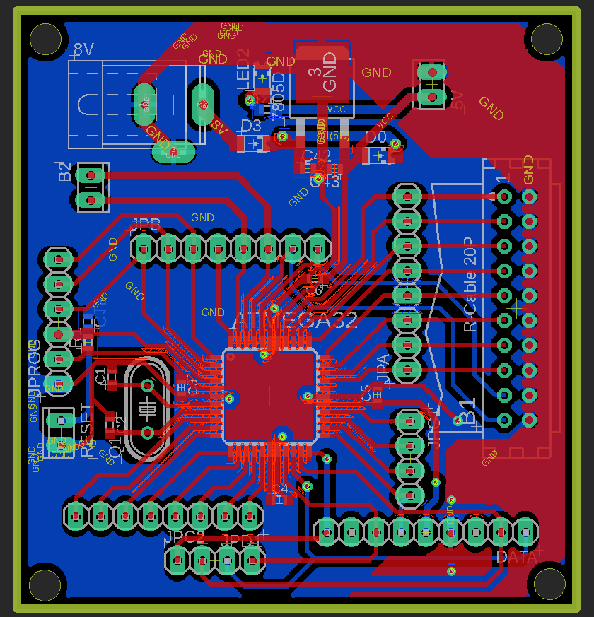


Here, is the actual PCB that was deployed on the robot from figure 2. I tried to keep it compact because the the mounting position of this PCB couldn't be predetermined during mechanical design considerations. Therefore, a compact design helped us mount this PCB almost anywhere on the bot as we wanted.

Circuit Components:
- ATMEL Atmega32 MCU: Micro-controller that provides a communication interface between a master micro-controller and PS2 controller.
- Crystal for Atmega32: Frequency
- 7805D SMD Voltage Regulator: Generates 5 V required by Atmega32 IC.
- LEDs, diodes, and RCL components: Power indicator LEDs. Voltage regulator protection diode. The exact values of these components can be found in the schematic image below.
- Connectors: PS2 Female connector, Header connectors, IC holders, relimates, Power Jack connector, berg strips.
Circuit Schematic: